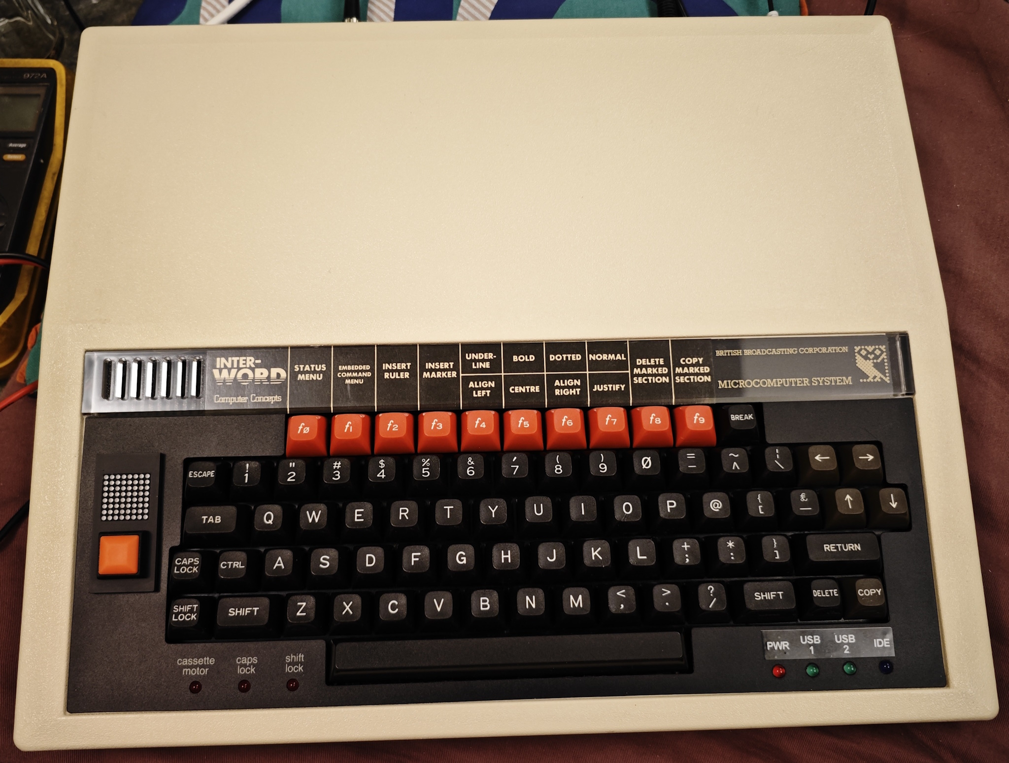
I grew up at a time where the BBC Computer Literacy Project was in full swing. It was a joint effort between the UK government and the BBC who worked with Acorn to develop a machine aimed at educational use. The most common variant was the BBC Model B, around 80% of schools had these computers generally with the standard Cub RGB monitor. These machines were where you would be exposed to BASIC programming, word processing (Interword was a popular installed ROM), LOGO and if you were lucky ‘computer clubs’ with floppy disks full of copied games. Yes really, the teachers were the source of them.
Everyone at home tended to have ZX Spectrums, Commodore 64s, or any other of the wide variety of 8 bit home microcomputers all competing at the time. It’s impossible to really convey how widespread home computing was, with consoles being rather rare by comparison. BBC computers were very well built however and very expensive – so almost nobody had them at home. I suspect this is why the games library is very limited compared to popular home machines, and … the joystick support sucked. You could buy official joysticks, but they’re analogue and not widely supported by software.
On a wild hit of nostalgia and impulse buying, I picked up a BBC on ebay because I wanted to enjoy playing Dare Devil Dennis and Killer Gorilla again – which was fun but time has not been kind to my hands and keyboard controls are often not the most ergonomic. So after failing to find anything that would solve this, I decided to make something.
The ZX81 had a similar (even worse) problem with keyboard gaming – but there’s a “programmable” joystick interface which actually lets you assign directions to keys using jumper wires on an expansion board – so I took that concept as inspiration. As an aside I’m STILL looking for one of those ZX81 interfaces if anyone has one for sale. That said, what I’ve come up with below can probably be adapted for the ZX81 with little to no changes other than code and wiring – that’ll be the next project.
To understand the concept, the following diagram is the BBC keyboard matrix. The columns are strobed and when a key is pressed the keyboard is scanned, a fairly common setup. Nearly all home computer keyboards work in a mostly similar way electrically.
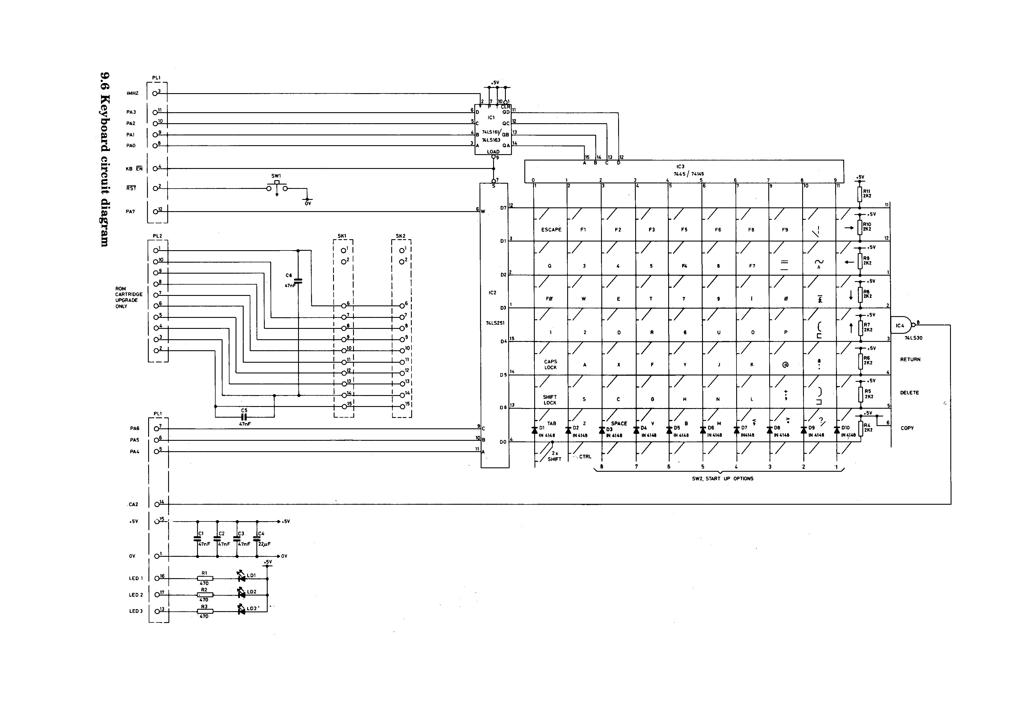
So given that what is essentially happening is we press a button and it shorts a column and row together, we could take a switch and solder it across the same points and it would do exactly the same as the key we soldered it to. An analogue switch chip can actually do the same thing – a simple CD4016 for example can connect a column and row together just like the physical switch can. Scale the theory up and an analogue crosspoint matrix can attach to all of the rows and columns at once, hijacking the entire keyboard. So I did.
I needed several things on what would become the interface PCB – a way to control the switch matrix, a way to plug a normal 9 pin Atari style joystick in, a way to program directions to keys on the fly and a way to visualise that programming – all without actually modifying the logical operation of the computer itself – it needed to be as close to physically separate as possible (aside from the whole matrix hijack thing). Then somehow this needed to be installable – I ended up designing it with multiple options in mind for that only because I wasn’t sure myself what I wanted to do and left all the doors open.
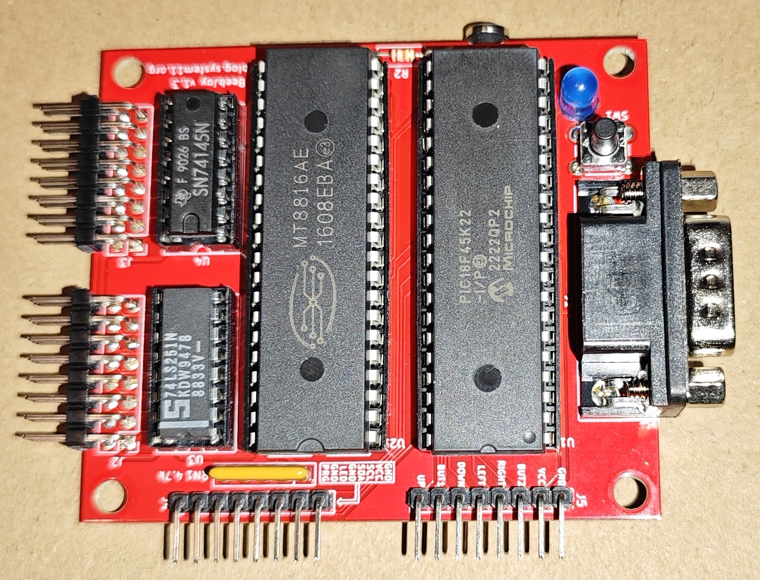
For control I went with a PICAXE chip – these are microcontrollers made by Revolution Education which use a dialect of BASIC. I’d played with them in other projects and while the language can be a bit limiting compared to something like an Arduino – the larger models have lots of IO pins and they’re simple to get started with. A MT8816 was selected as the matrix chip, one of the few 5v through hole options with a big enough matrix.
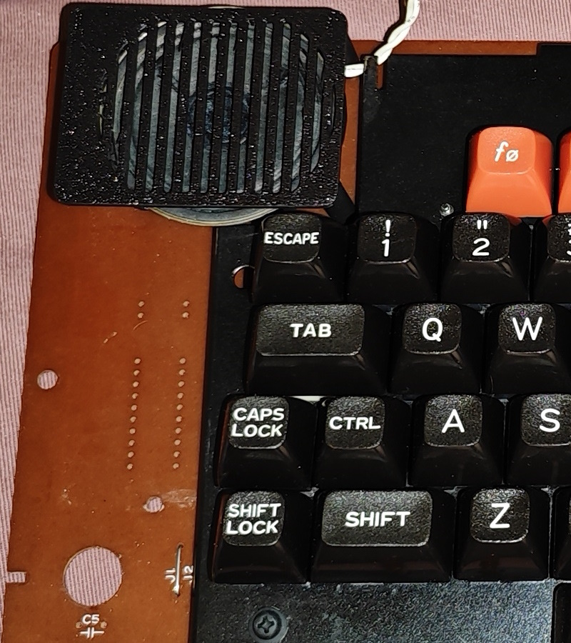
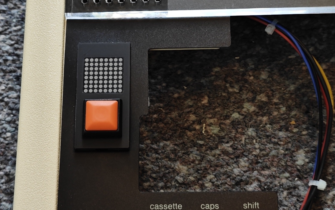
Since I wanted to make a completely onboard solution for my own install I decided to use the “ashtray” – on 99% of machines this is a perforated plastic cover in the keyboard area of the case top which you could punch out and put a serial ROM reader in. These were VERY widely vandalised by curious children, to the point where a 3D printed cover is now available – which I modified to hold an I2C display and programming button.
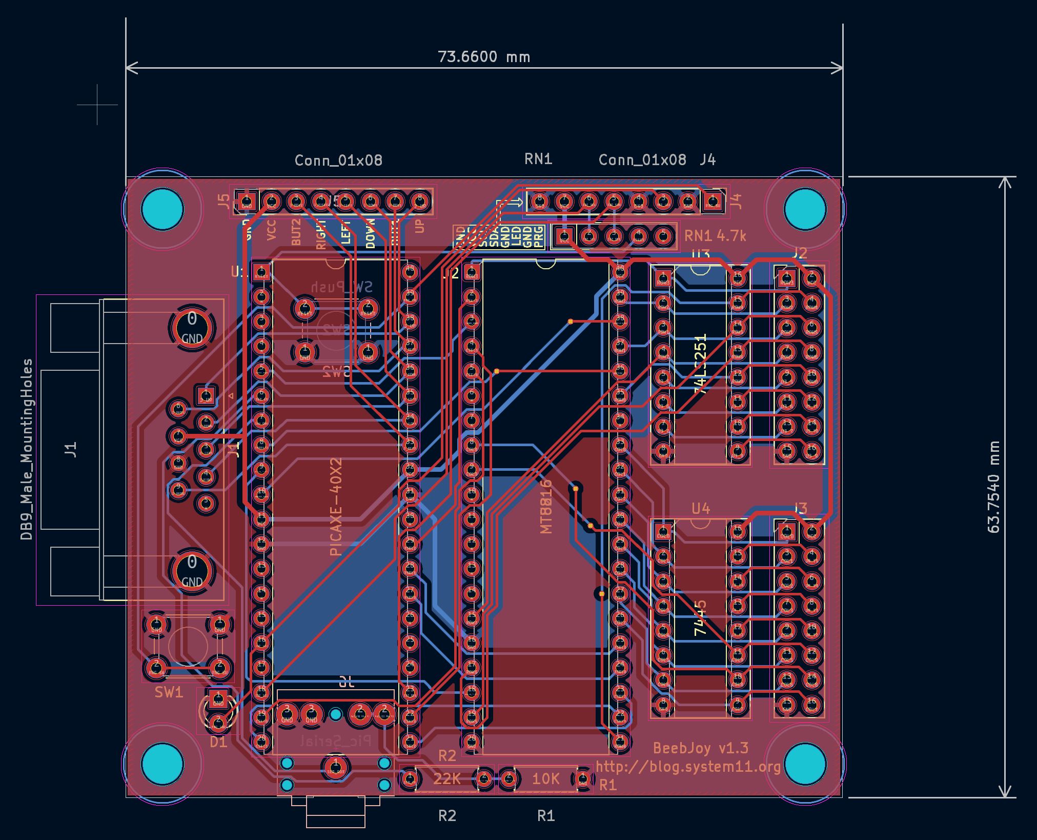
The PCB design was relatively simple if time consuming due to the number of tracks – on the PICAXE about 10 IO lines were needed to control the MT8816, one for the programming button and LED, a few for I2C display control and 6 for reading joystick inputs (I decided early on to support the rare 2 button joysticks). For joystick connection I simply used a 9 pin socket on the PCB and a pin header. I added a programming button, LED and a pin header for those plus the I2C 8×8 LED display.
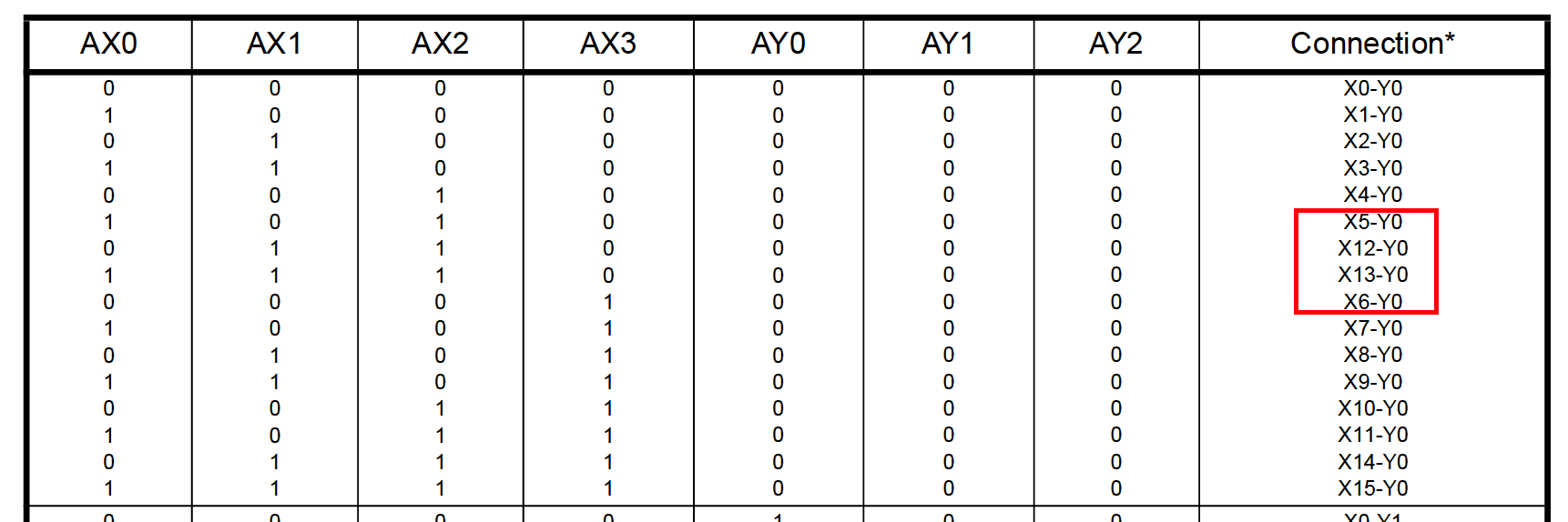
PICAXE chips are programmed using a reset circuit and a serial jack so I put those on the back of the PCB to save space. The MT8816 had to have columns and rows connected to all the keyboard matrix column and row drivers. Actually this is where the single largest problem with the project occurred – it was put on hold for years at one point because it wouldn’t work for all keys and I parked it – one day when revisiting the problem I noticed in the datasheet that the MT8816 address lines weren’t perfectly sequential which turned into yet another PCB run to fix.
Not all BBC keyboards are physically the same – on some there’s a metal shield which makes accessing the matrix column and row chips difficult, on others these are totally exposed. I added sockets on the interface PCB so that one option was to relocate the chips from the keyboard and replace them with sockets. With the metal shield keyboards really the only option is to solder to the bottom of the keyboard PCB at the chip pins.
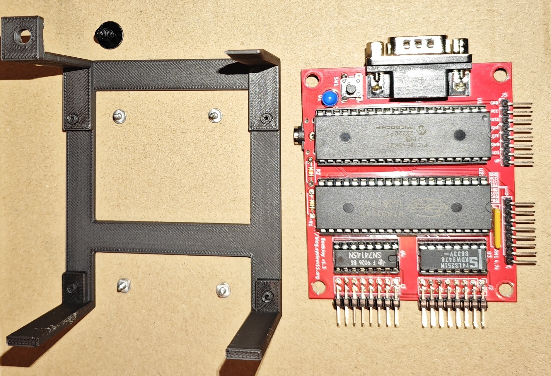
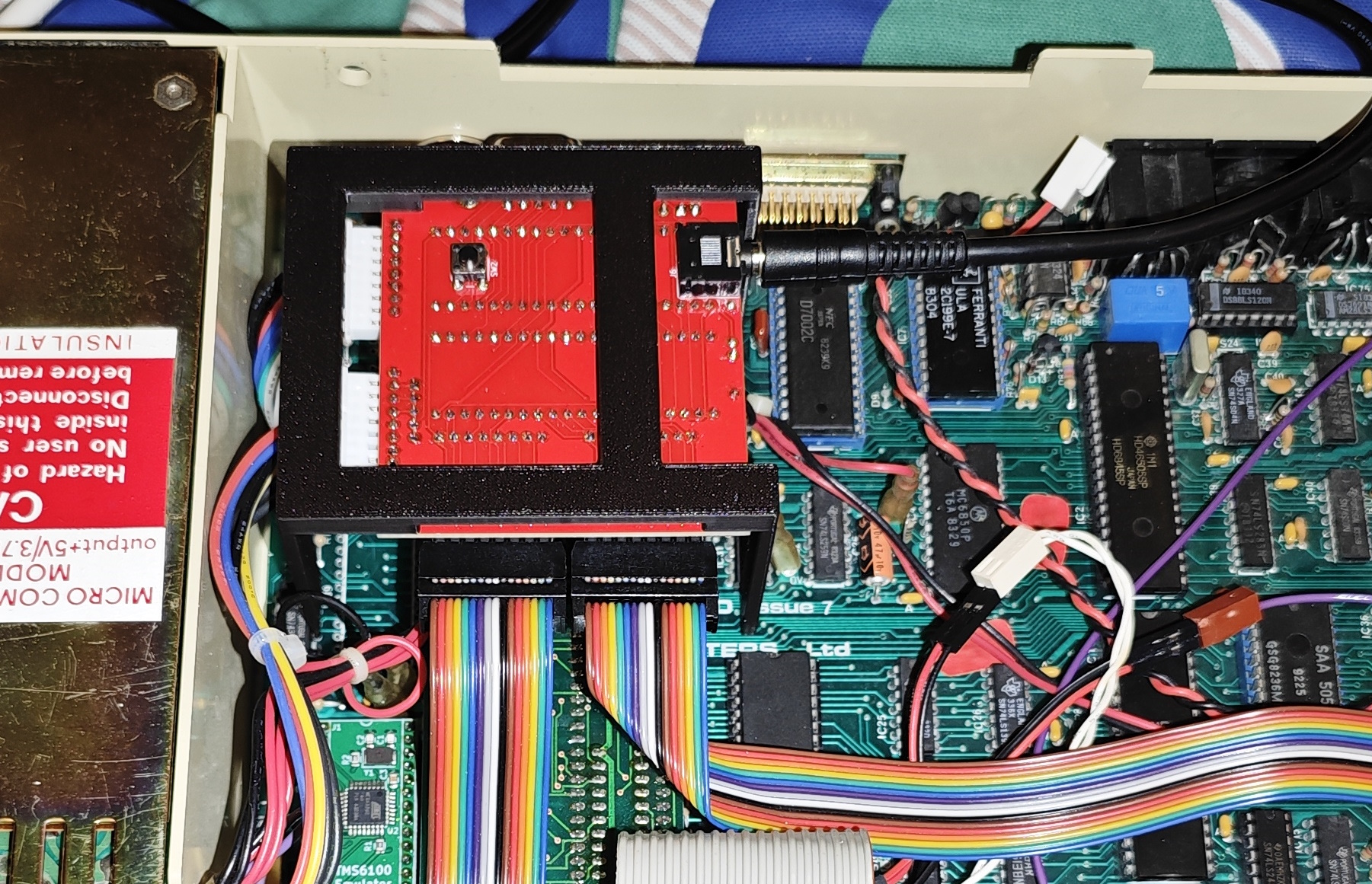
The end result is a PCB which you can install inside the computer (after experimenting with adhesive PCB feet a bracket was designed), or if you can find a way to extend the row and column pins outside the case (giant ribbon through the air vent for example), you could also put it in a plastic case for an external option.
A general overview of operation is that the PICAXE keeps checking the joystick inputs to see which directions are pressed, this is represented as a joystick current state and it just loops until the state changes or the programming button is pressed. Programming mode lets column and row of the keyboard matrix be selected, displaying the key in the I2C display – this is stored as a bit representation of the column and row. The MT8816 switches are turned on or off by setting the X and Y address lines to select column and row and setting the data pin to 0 or 1. When the joystick state does change (for example we pressed left or released the fire button), it sets the stored matrix positions for all inputs into the MT8816 at once by using the stored bitfields on the address lines and 0 or 1 to the DATA input. That’s literally it. The restrictive nature of the PICAXE BASIC dialect made some of this a bit tricky or uglier than it needed to be but it works, and at the end of the program code is a massive field of hex data defining the 8×8 representations of the keys.
The single worst part of the coding was where I changed the type of display I was using to one which was at 90 degrees, and all that data needed changing. I wrote a Python script to do it in the end. I used grok to help learn because I’d never used Python before, only Perl. Lots of “how do I do X in Python if I did Y in Perl?”, it was genuinely easier than reading a book.
How to build & install
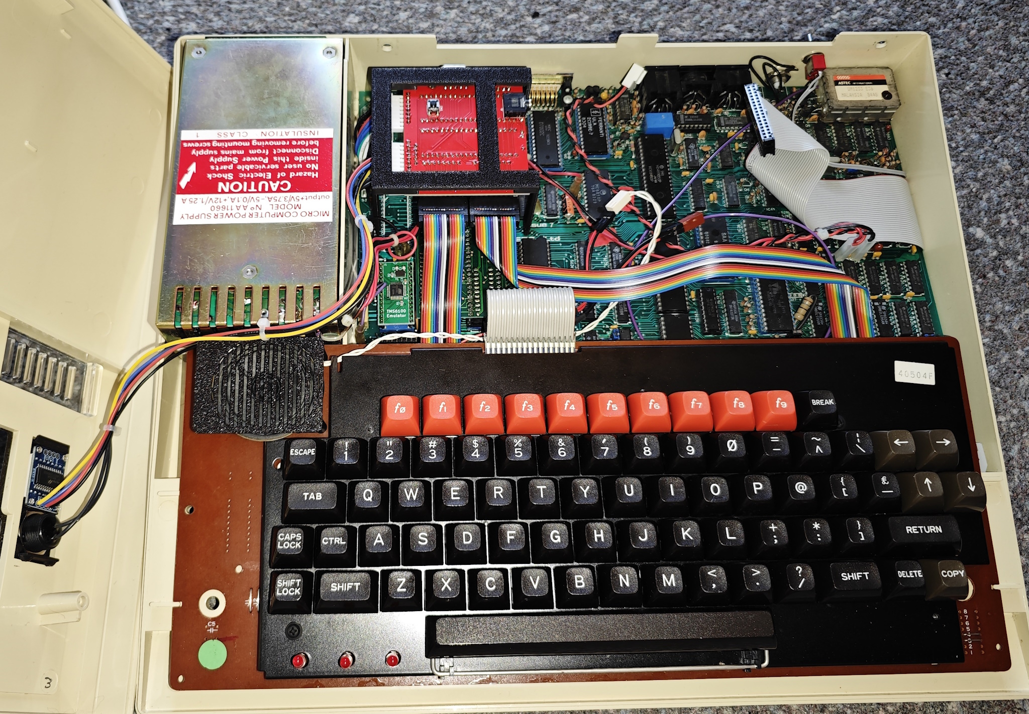
There are a few ways to assemble and install this, so I’m going to document my preferred installation approach using my “nice” BBC which is a Model B with a Retroclinic Datacentre installed. Since it’s already modified I won’t have to worry too much about pushing out the ashtray cover on a perfect example. I’ll be providing parts lists, code, 3d models and so on – I only ask two things. Firstly if you do make a modified version or project based on this, please link back to the article and I’d love to see it if you tag me on X. Secondly please don’t make and sell these for profit without contacting me to discuss, I was very surprised to find one of my projects on ebay a while back.
PCB Build
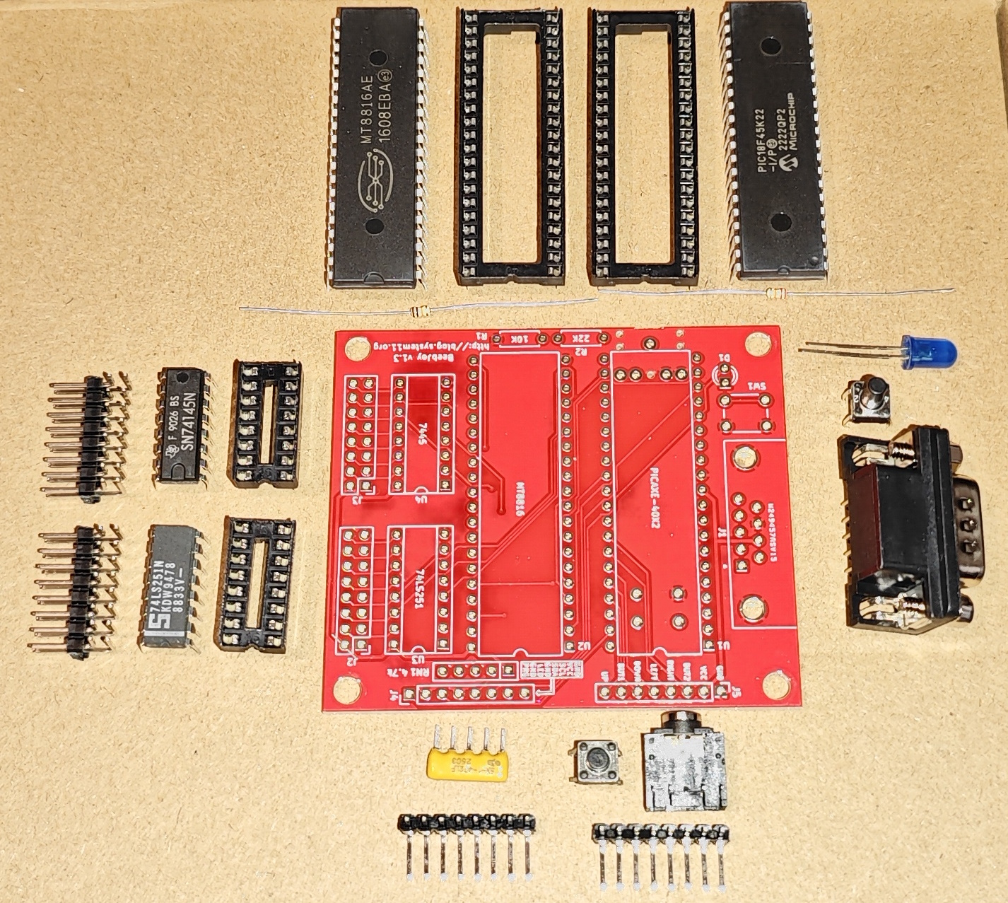
PARTS LIST
1x PICAXE 40X2
1x Stereo PICAXE Connector
1x 6x6mm 4mm depth through hole push switch
1x 10k 0.25w 6.3mm resistor
1x 22k 0.25w 6.3mm resistor
1x MT8816
2x DIP40 socket
1x 4.7k Ohm 5-pin SIP resistor array
1x 10-pin 2.86mm pin header 90 degree
2x 2x8-pin 2.86mm pin header 90 degree
OPTIONAL
1x DB9 connector THT, male (ex RS 771-8307)
1x 3mm LED
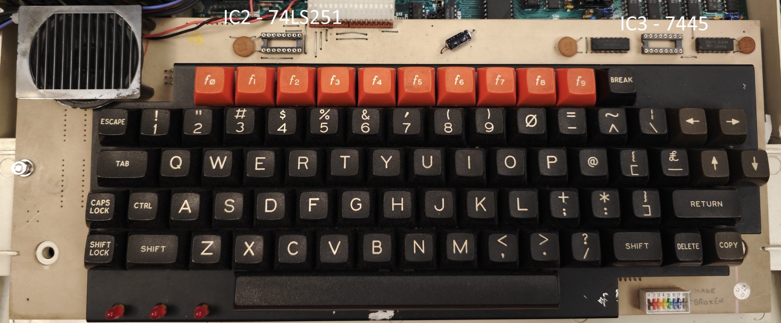
1x 74LS251
1x 7445 / 74145
2x DIP16 socket
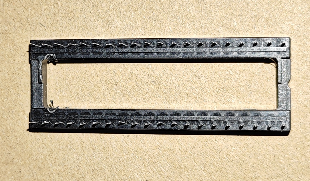
1x 10-pin 2.86mm pin header 90 degreeStart by fitting the PICAXE stereo connector and the pushbutton switch to the reverse side of the PCB, before soldering the outermost pins of the stereo connector, bend them in slightly. Next take one of the sockets and file or melt slight recesses into the sides as shown.
Fit this socket above the PICAXE port then populate all remaining parts. Note that depending on install approach some parts are optional – the DB9, LED and second push button are not required if fitting inside the case, the sockets and chips for the 74LS251 and 7445 are optional depending on keyboard attachment method, and the J5 10-pin header isn’t required if using the DB9. For demonstration purposes this one is being fully populated regardless.
Interface bracket build
PARTS LIST
1x 3D printed interface bracket
1x BeebJoy interface
4x M1.7 x 5mm pozi flanged self tapping screw
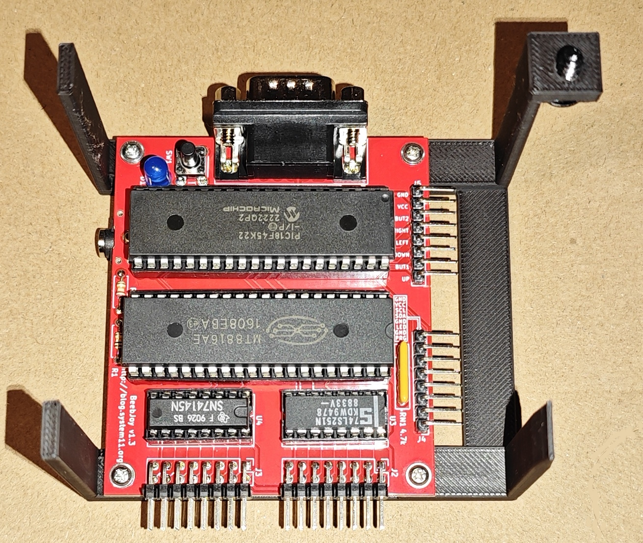
1x No 8 x 1/2" pozi flanged self tapping screwFit the interface PCB to the bracket as shown, care should be taken – the holes are pre drilled but not tapped.
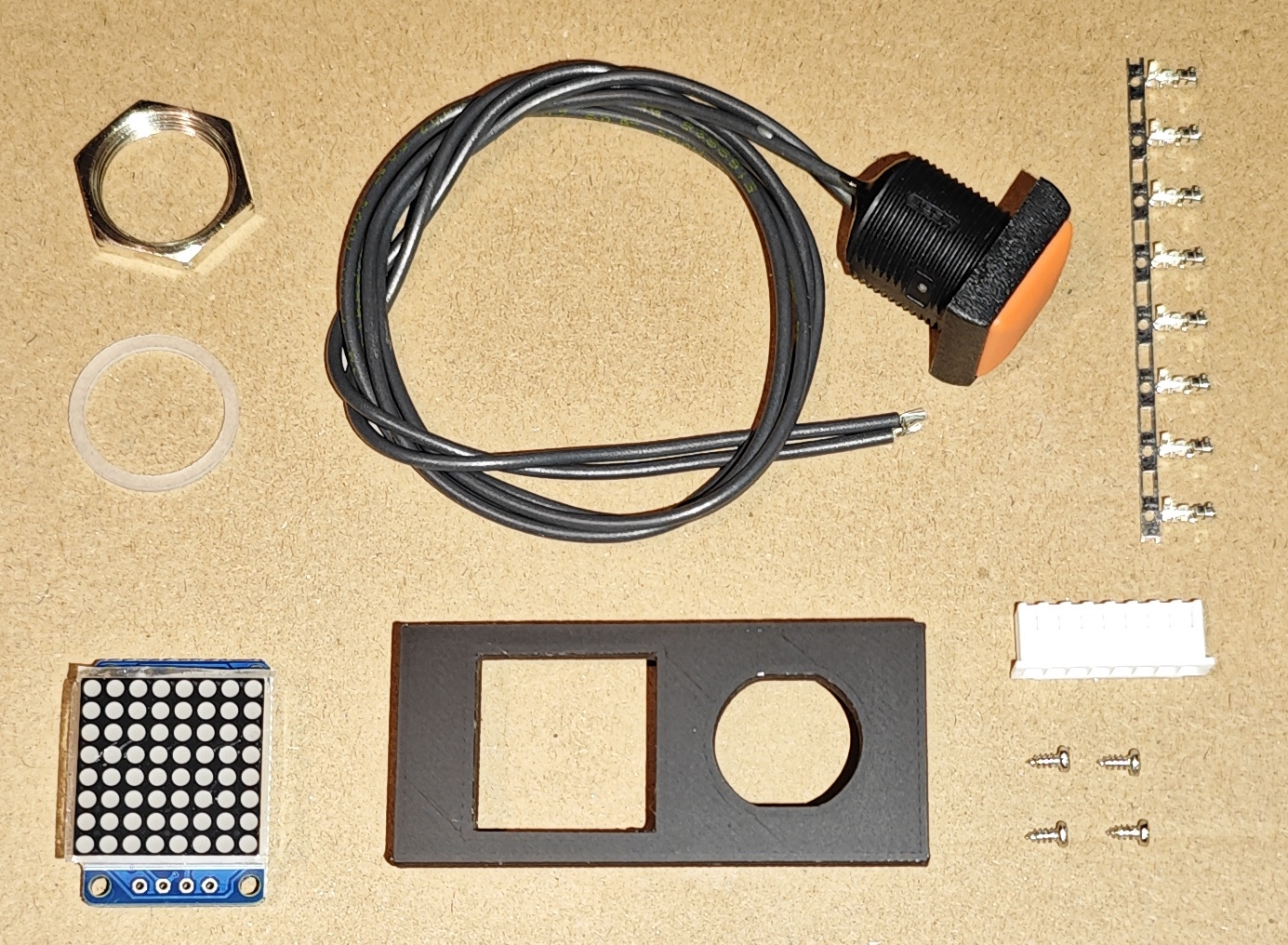
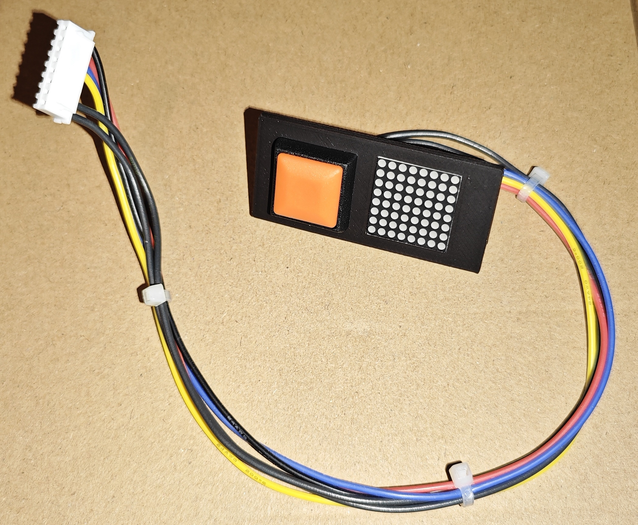
Ashtray panel build
PARTS LIST
1x 3D printed ashtray cover
1x 788AS 20x20mm I2C LED display
1x APEM IRC3F492 Orange Square 16mm Momentary NO Push Button Switch Prewired
4x M1.7 x4mm self tapping screw
6x JST XH male crimp connector
1x JST XHP 8-pin connector housing
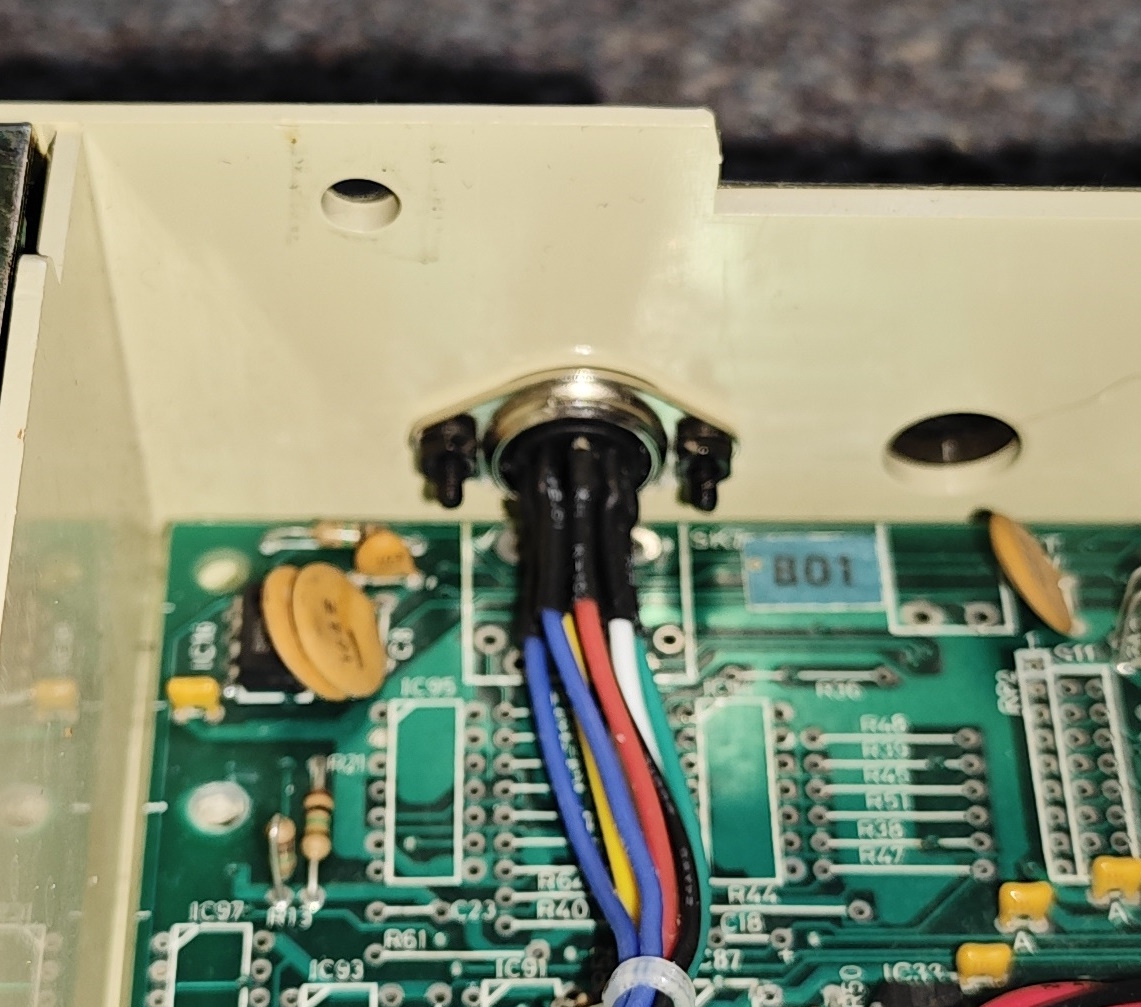
4x 31cm wire lengthsThe I2C module has two sets of solder points. Placing it face down with the chip oriented vertically and pin 1 at the top, use the right hand set of pins. If you get this wrong the display will be upside down which is quite annoying. The gap in the mounting points on the back of the 3D printed cover is for the soldered wire ends to protrude. Solder the wires to the module. Next fit the push button, you won’t need the rubber ring – just do the large hex nut up, it’s slightly difficult due to space but will fit. Next fit the display module and fix with 4 screws – you may need to file the corners of the 3D print a bit if the module is too tight, be careful not to mark the top surface doing so. The screws will self tap without cracking due to infill density or you could carefully pre-drill them. Bend the wires upwards from the cover to form the loom curve that will sit in the space under the ashtray and ziptie in place. Cut the switch wires to the same length as the display wires, then attach 6 crimp connectors and pin as following – note that on the PCB J4 and J5 pin order is different, the pin 1 markings are accurate.
| J4 PIN | FUNCTION | ASHTRAY PIN |
|---|---|---|
| 1 | PRG switch | switch pin 1 |
| 2 | GND | switch pin 2 |
| 3 | PRG LED | |
| 4 | GND | |
| 5 | I2C SDA | display SDA |
| 6 | I2C SCL | display SCL |
| 7 | VCC | display VCC |
| 8 | GND | display GND |
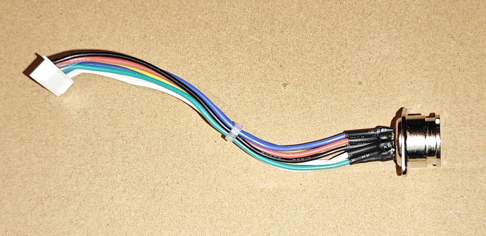
Econet joystick loom build
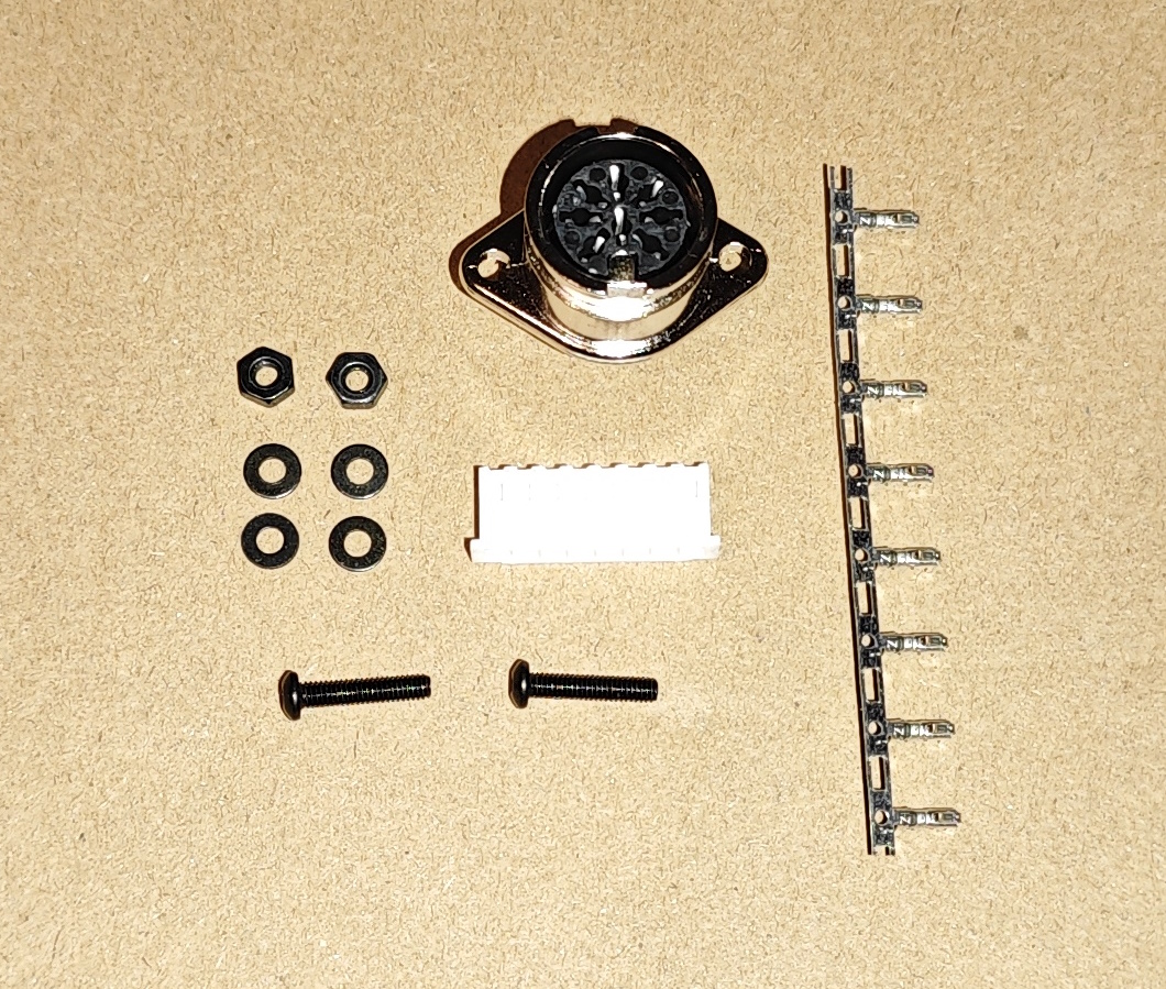
PARTS LIST
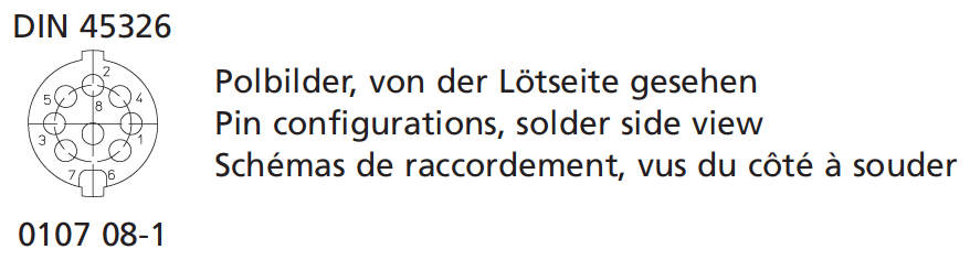
1x Lumberg 0107 08-1 8 Pin DIN Female Chassis Socket DIN 45326 Bayonet Lock Flanged
2x M2.5 x12mm machine screw
4x M2.5 washer
2x M2.5 nut
8x JST XH male crimp connector
1x JST XHP 8-pin connector housing
8x 13cm wire lengthsPut the screws to one side. Starting with the GND wire in the middle, solder all wires to the DIN connector, then crimp and insert wires in the connector housing using the following pinout:
| J5 PIN | FUNCTION | DIN PIN |
|---|---|---|
| 1 | GND | 8 |
| 2 | VCC | 2 |
| 3 | Fire 2 | 5 |
| 4 | Right | 3 |
| 5 | Left | 1 |
| 6 | Down | 7 |
| 7 | Fire 1 | 4 |
| 8 | Up | 6 |
Econet to Joystick adapter
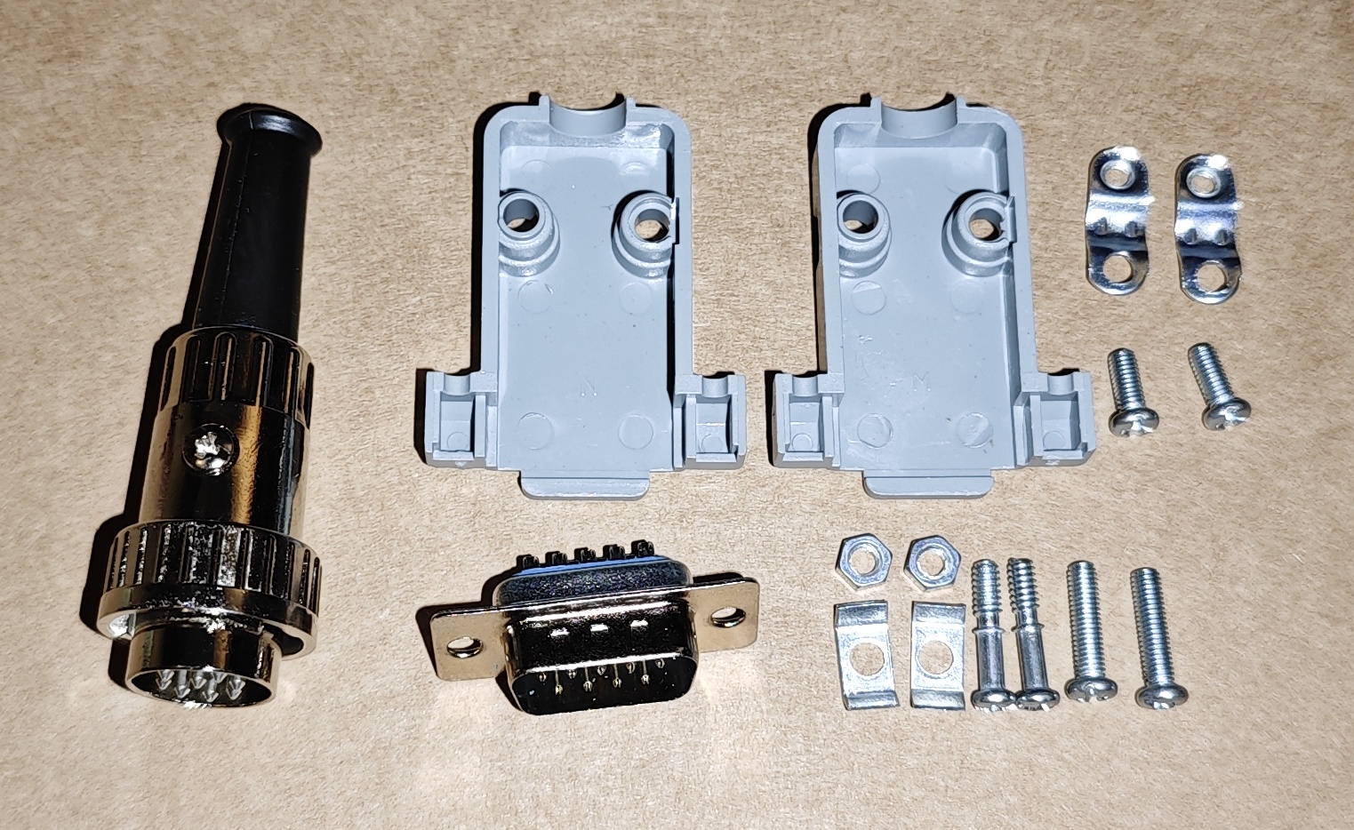
PARTS LIST
1x Lumberg 0132 08-1 8 Pin DIN Male Straight Plug DIN 45326 Bayonet Cable Mount
1x DB9 male connector housing
8x wire lengths
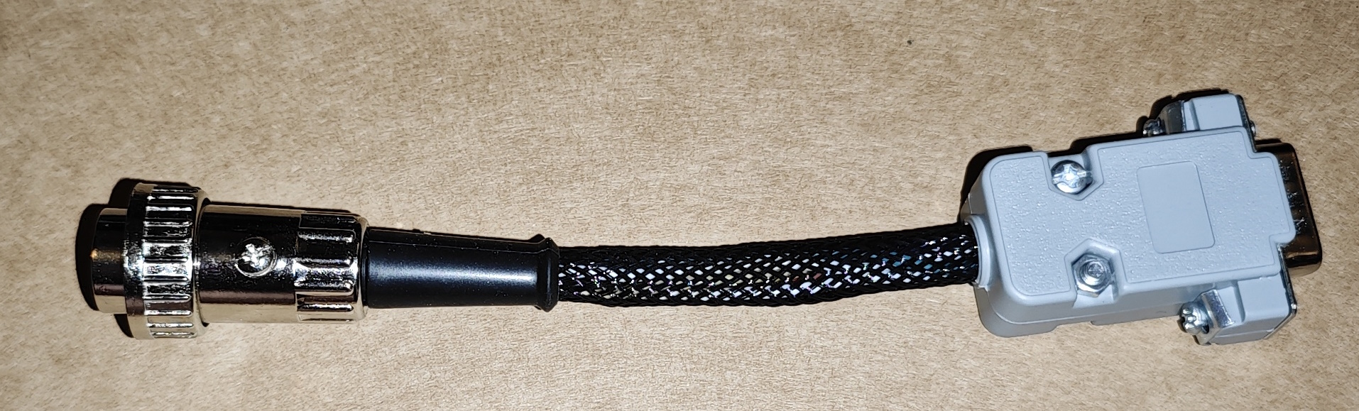
1x braided cable sheathUse any wiring you like for this – a piece of old joystick multicore cable will be fine too. Remove the screw from the DIN connector, the pins pull out from the front. Solder the wires to the correct pins as per the pinout below starting with pin 8/GND and pinch the cable strain tabs over the wires. If wanting to build one with the braid exactly as pictured, push a section of braid through the rubber boot of the DIN connector then thread the wires into it, insert the pin assembly and replace the screw (make sure the DIN plug lock ring is on the end of the plug as the screw is what stops it moving up the cable). Fit the DB9 connector on the other end.
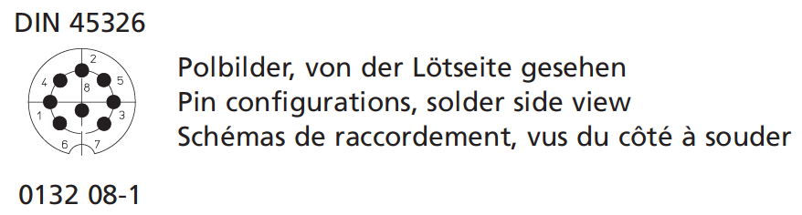
| DIN PIN | FUNCTION | DB9 PIN |
|---|---|---|
| 1 | Left | 3 |
| 2 | VCC | 7 |
| 3 | Right | 4 |
| 4 | Fire 1 | 6 |
| 5 | Fire 2 | 9 |
| 6 | Up | 1 |
| 7 | Down | 2 |
| 8 | GND | 8 |
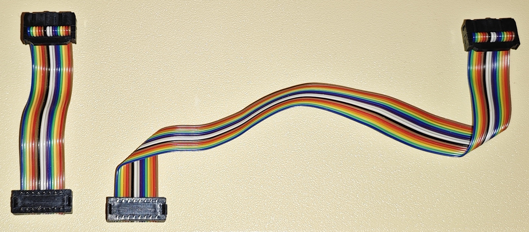
Keyboard ribbons
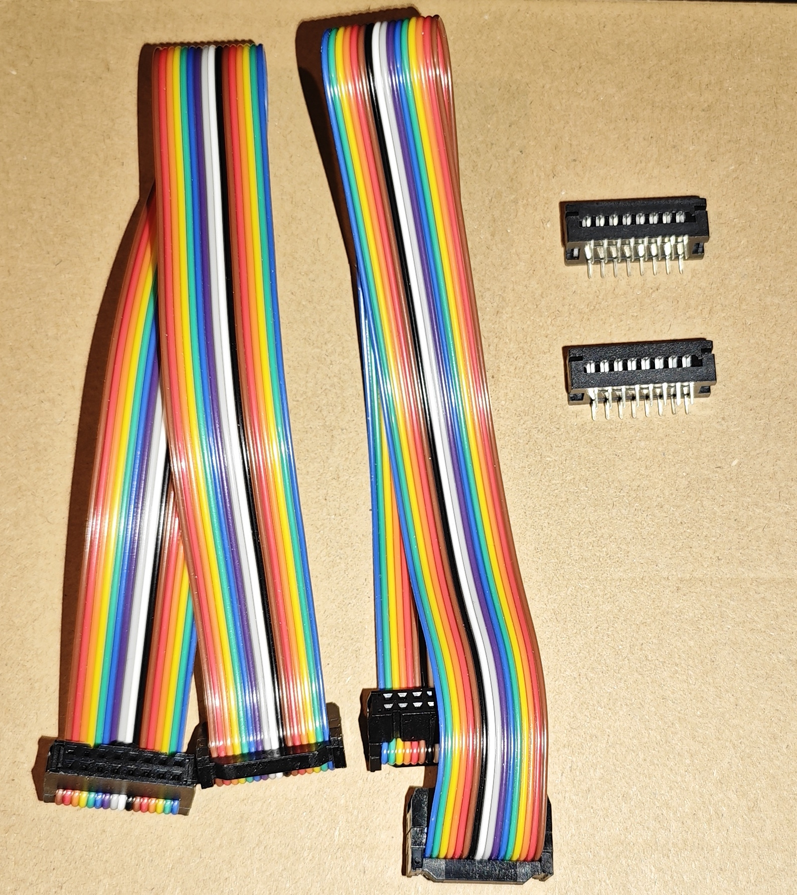
PARTS LIST
2x Fc Color Line 2.54 16 Pin Flat Ribbon IDC Box Header
OPTIONAL
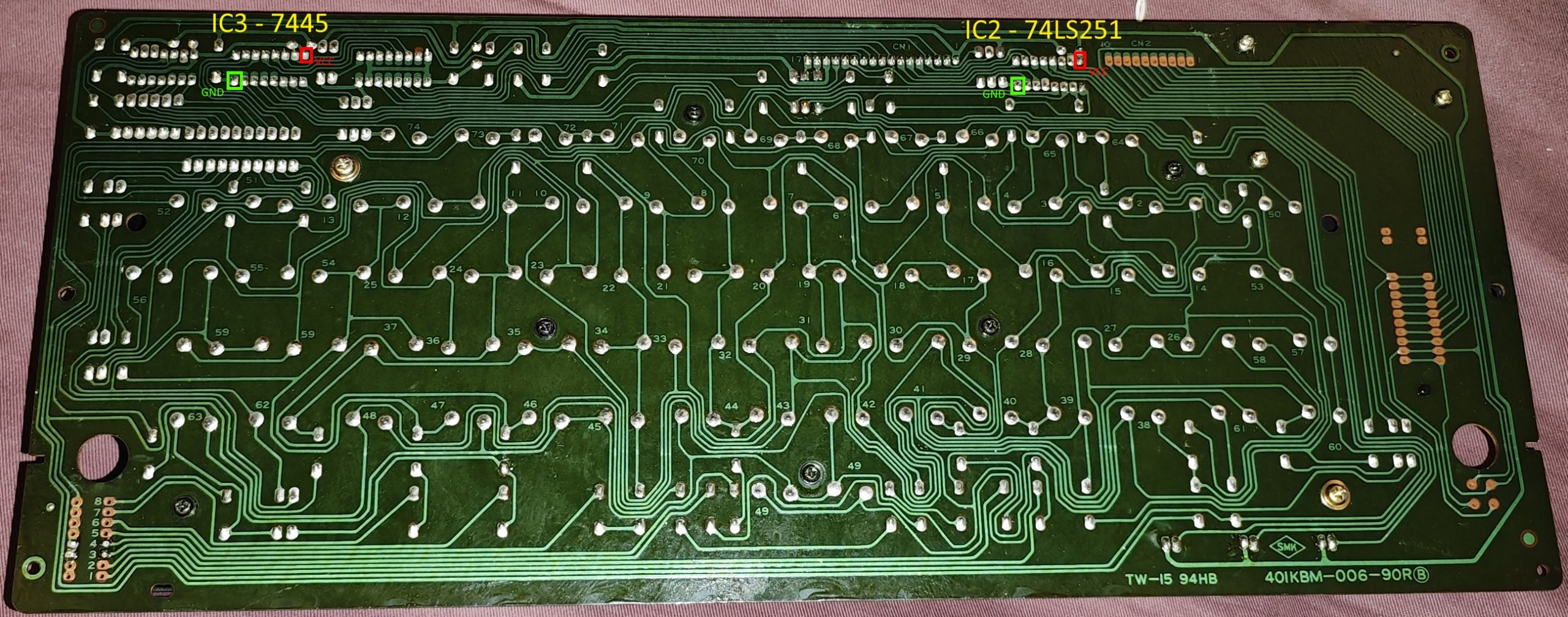
2x 2.54mm 16-pin Pin Male Header FD IDC Socket Cable Connector 3100-16PDepending on which revision of model B you have, you can choose whether to offboard IC2 (74LS251) and IC3 (7445) or solder ribbons directly to the underside of the chips. If offboarding they can be replaced with turned pin sockets in which case you may want to fit IDC socket connectors. Note that Most connectors have the wrong pin layout and have pins 1-8 and 9-16 on the wrong sides, pin 1 MUST match the location of pin 1 on the chip. The correct part is linked in the links section at the end of this article. Cut one ribbon cable to 95mm and the other to 268mm. J2 and J3 pinouts are below but this is just for reference as this is all a 1:1 mapping physically, it just looks different as IDC pin numbering is different to DIL numbering.
| J2 PIN | FUNCTION | IC2 PIN (74LS251) |
|---|---|---|
| 1 | ROW 3 | 1 |
| 2 | VCC | 16 |
| 3 | ROW 2 | 2 |
| 4 | ROW 4 | 15 |
| 5 | ROW 1 | 3 |
| 6 | ROW 5 | 14 |
| 7 | ROW 7 | 4 |
| 8 | ROW 6 | 13 |
| 9 | U3_5 | 5 |
| 10 | ROW 0 | 12 |
| 11 | U3_6 | 6 |
| 12 | U3_11 | 11 |
| 13 | U3_7 | 7 |
| 14 | U3_10 | 10 |
| 15 | GND | 8 |
| 16 | U3_9 | 9 |
| J3 PIN | FUNCTION | IC3 PIN (7445 / 74145) |
|---|---|---|
| 1 | COL 0 | 1 |
| 2 | VCC | 16 |
| 3 | COL 1 | 2 |
| 4 | U4_15 | 15 |
| 5 | COL 2 | 3 |
| 6 | U4_14 | 14 |
| 7 | COL 3 | 4 |
| 8 | U4_13 | 13 |
| 9 | COL 4 | 5 |
| 10 | U4_12 | 12 |
| 11 | COL 5 | 6 |
| 12 | COL 9 | 11 |
| 13 | COL 6 | 7 |
| 14 | COL 8 | 10 |
| 15 | GND | 8 |
| 16 | COL 7 | 9 |
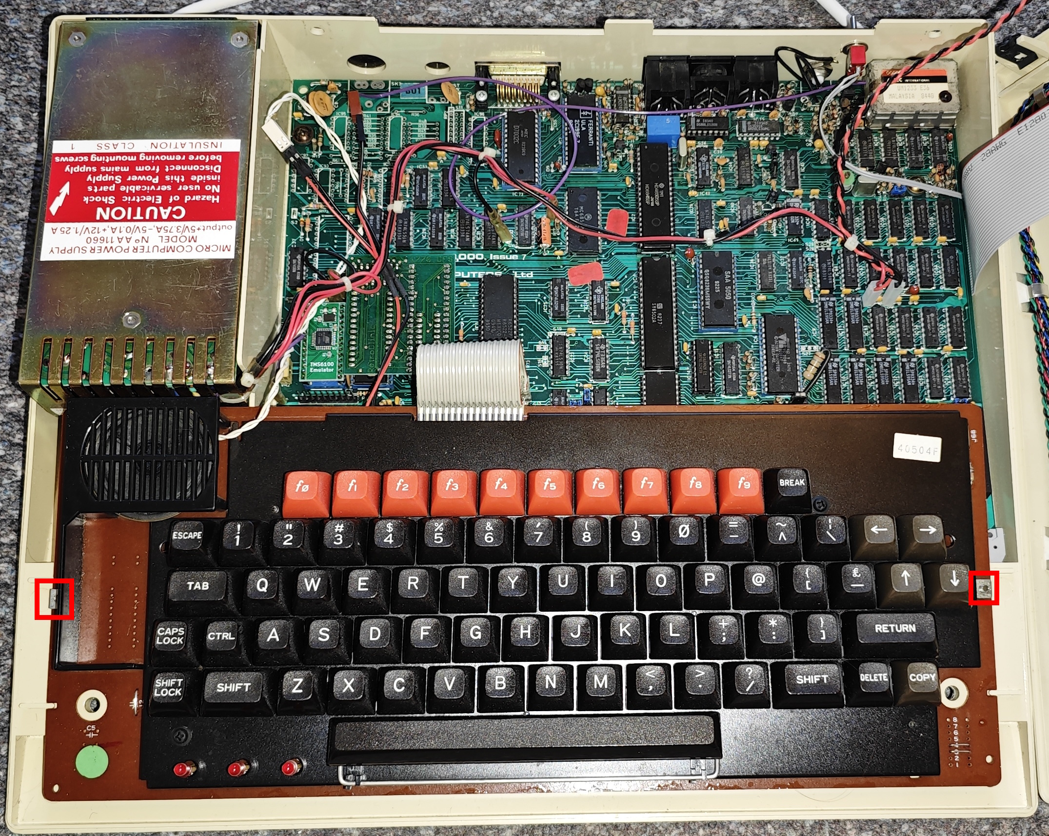
Installation procedure
As mentioned this example fitting is using my already slightly modified machine with a Retroclinic Databank installed, speech chip and ADFS upgrade. There are slight differences between older units and the BBC Model B “plus”, the key difference will come down to the keyboard model mentioned earlier – the original machines have exposed chips and the plus have a metal shield in the way.
Remove the 2 screws under the front of the keyboard and the 2 on the back panel to release the top case cover. Remove case cover and the remove the screws and nuts from the left and right side of the keyboard. Unplug the large grey keyboard ribbon and remove the keyboard.
For older units the cleanest install is to remove IC2 (74LS251) and IC3 (7445) and replace them with turned pin sockets – if going with this option as mentioned earlier these chips will need to be installed on the interface board.
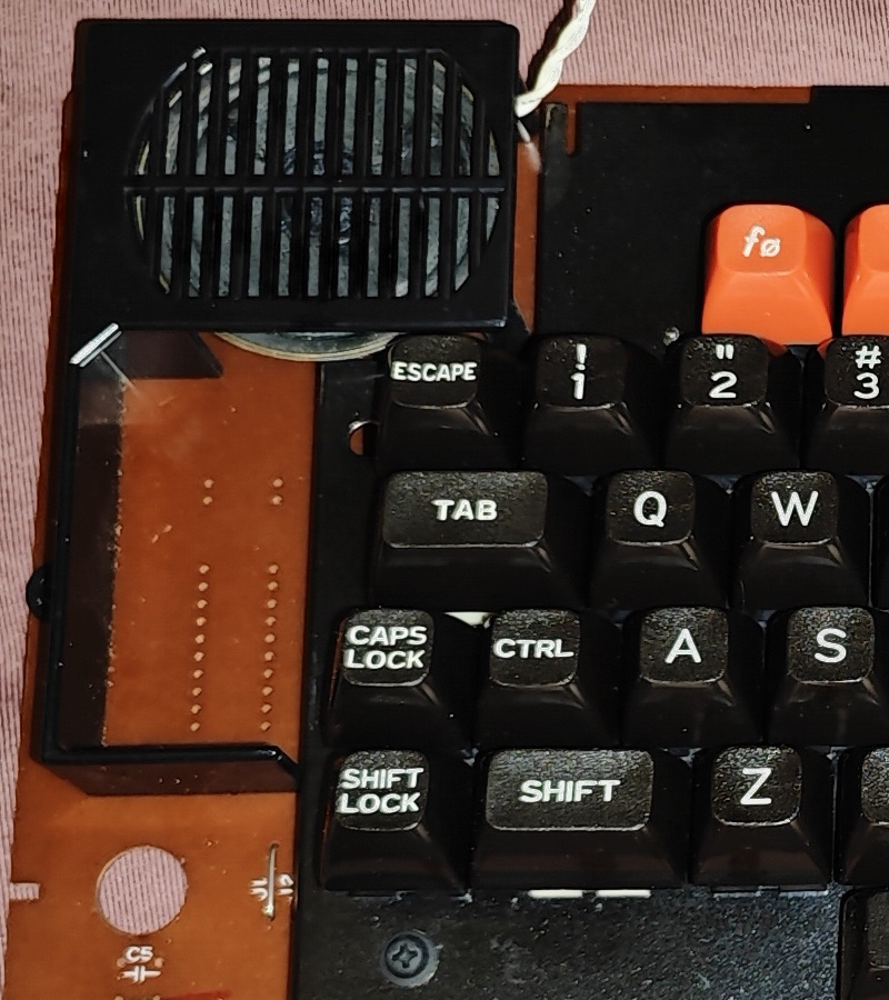
If you have the metal shield keyboard, more work is required – the plastic speaker shield extends around the ashtray area on the left of the keyboard. You can either break this extension off, or replace the grill entirely with a 3D printed one in the old style.
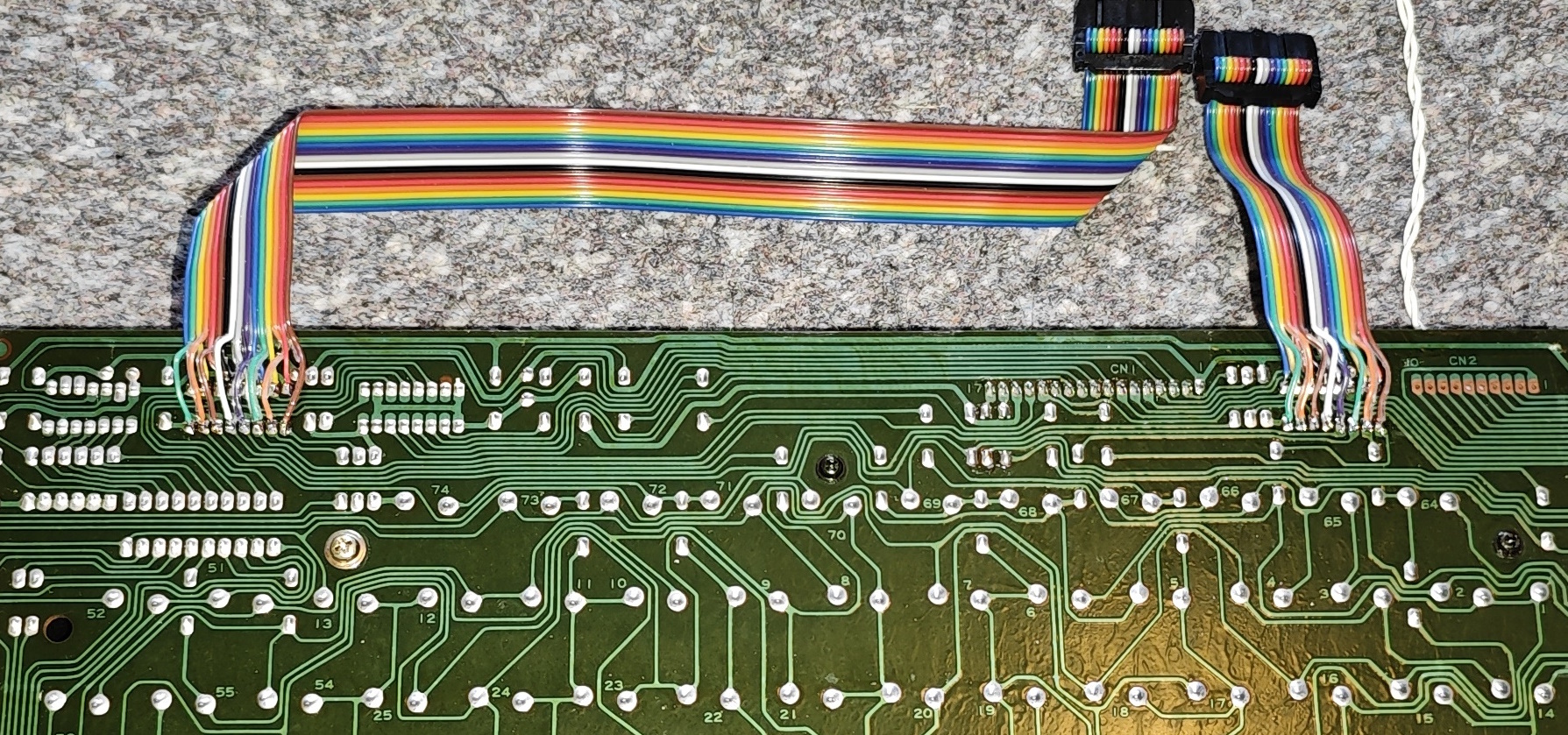
If using the older keyboard and sockets plug in the ribbons. If using the newer keyboard or wanting to leave the TTL chips on the old type keyboard turn it upside down, you will have to solder all 16 wires of each ribbon underneath the relevant chips – refer to the below photo and the wiring pinout from earlier.
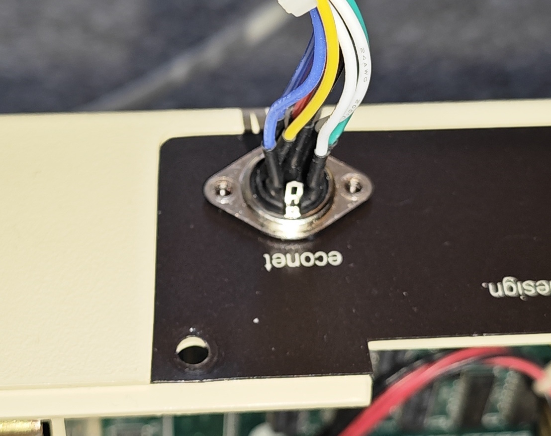
On the back of the machine, push through the perforated econet cover. Take the econet joystick loom and push the DIN 8 in from the outside, use the flange holes to line up and drill a 2.5mm hole on each side. Install econet joystick loom into machine, secure with bolts washers and nuts.
Push out the perforated ashtray cover on the computer case top cover, thread ashtray panel loom through from the front, then clip assembly into place hooking in the top edge first.
Refit keyboard, grey keyboard ribbon and screws, remove the motherboard screw and fiber/plastic washer from near the econet joystick loom. Loosely install the joystick interface bracket while attaching the econet joystick loom, ashtray panel loom and both keyboard ribbon cables ensuring correct pin locations for each.
Perform an electrical safety check! Where U3 and J1 are mentioned it doesn’t matter if they haven’t been populated, just check using the correct pads or socket positions. Use a meter on continuity test for the following checks:
- Check there is no connection between pin 8 and 16 of U3 on the joystick interface.
- Check that pin 8 of U3 has connection to the ground pin (bottom left) of any TTL chip on the motherboard or the modulator shield.
- Check that pin 16 of U3 connects to the 5v/VCC pin (top right) on any TTL chip.
- Check that pin 8 on J1 connects to pin 8 on U3.
- Check that pin 9 on J1 connects to 16 on U3.
- Check that pin 8 of the econet joystick port connects to the GND pin on any motherboard TTL and pin 2 to 5v/VCC on any TTL chip.
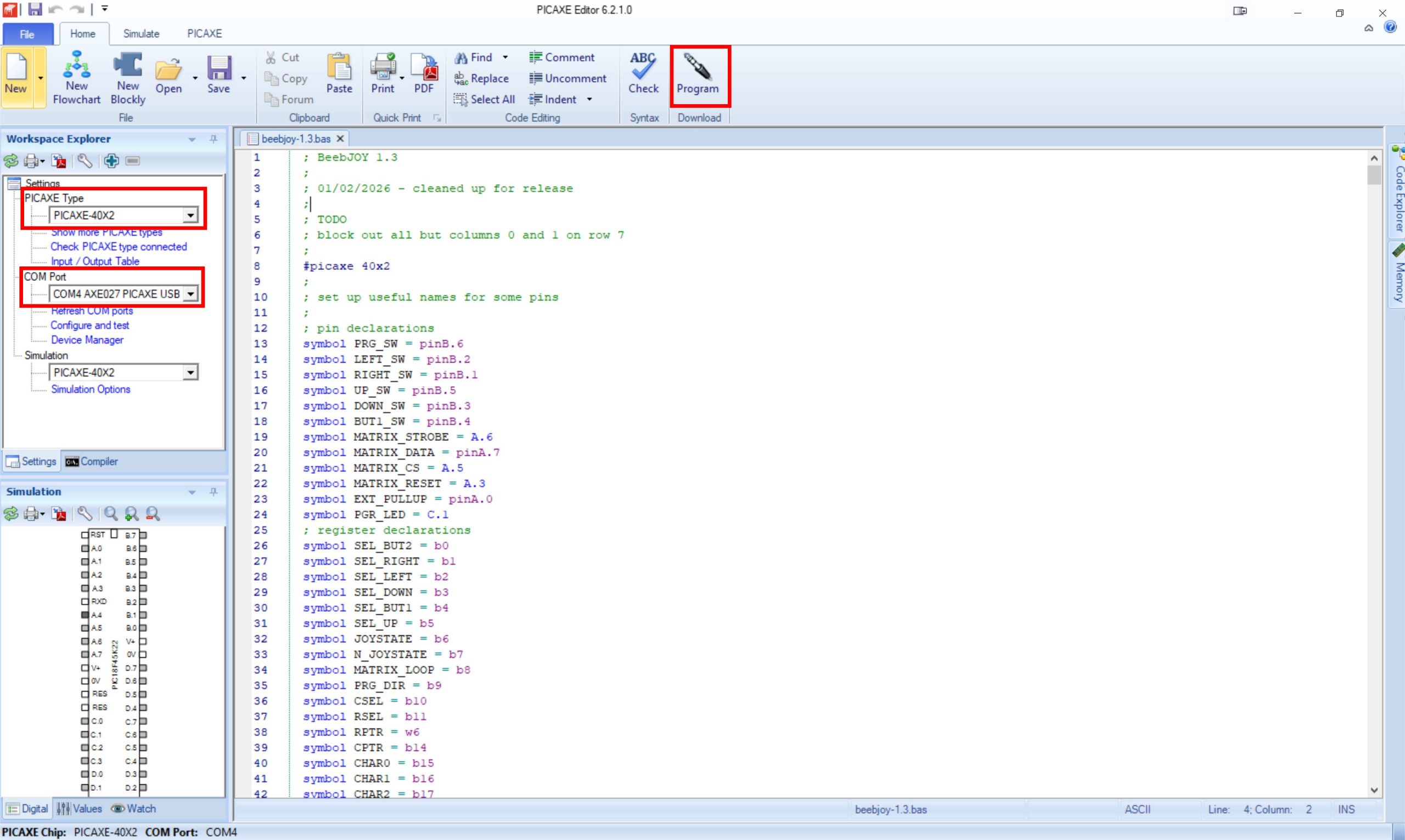
If the PICAXE chip needs programming, plug the AXE027 cable into the 3.5mm port on the interface and a USB port on your computer.
Load PICAXE editor and open beebjoy-1.3.bas. Set the correct chip type and port in the top left, turn on the BBC and then click Program in the top right. If the programming fails to initiate try again and quickly press the reset button on the back of the interface. Power off BBC.
Plug a joystick into J1 or the econet joystick port adapter, turn the BBC on and push up down left right and fire, you should see ZX:/ and an error message from return being pressed. Press the programming button on the ashtray or on the chip side of the interface PCB, check that the I2C display or programming LED react to direction presses. Turn off BBC.
Use the new longer screw motherboard screw with the original fiber or plastic washer to screw down interface bracket. Replace case top cover and fit screws to bottom/rear.
Usage
Using this is significantly easier with the I2C display but the programming LED tries to feed back with flashes. The interface has no storage ability – every time the machine is power cycled it will revert to defaults which are Z X ; / and return (the controls for Killer Gorilla which inspired the entire project).
- Press the programming button on the ashtray or interface. The display will show a BBC owl symbol, the programming LED should stay lit.
- Press the direction or button you wish to program – the interface supports 4 directions and 2 buttons (uncommon but these sticks do exist). The display will show ESC which is row 0 column 0 of the keyboard matrix, the programming LED will go out.
- Using the 4 directions you can move around the logical keyboard matrix columns and rows – the display will show the key at that position (or an inverted X if the key is invalid), the programming LED will simply flash each time it changes. Press joystick button 1 to reset to 0,0 again if you get lost.
- When the correct key is selected press the programming button again. The display will show the BBC owl again and go out, the LED will flash and go out.
Use the below reference table for the keyboard matrix layout.
| ESC | f1 | f2 | f3 | f5 | f6 | f8 | f9 | | | RIGHT ARROW |
| Q | 3 | 4 | 5 | f4 | 8 | f7 | = | ~ | LEFT ARROW |
| f0 | W | E | T | 7 | 9 | I | 0 | £ | DOWN ARROW |
| 1 | 2 | D | R | 6 | U | O | P | [ | UP ARROW |
| CAPS LOCK | A | X | F | Y | J | K | @ | : | RETURN |
| SHIFT LOCK | S | C | G | H | N | L | ; | ] | DELETE |
| TAB | Z | SPACE | V | B | M | , | . | / | COPY |
| SHIFT | CTRL |
Links and downloads
Revolution Education PICAXE manuals
Revolution Education – PICAXE software (get PICAXE Editor 6.2.0, 6.2.1 patch, AXE027 driver)
BeebJoy 1.3 shared project at PCBWay
Original source of ashtray cover model by Steve Bubs