The Toshiba SD-B100 DVD player is the model used by Seibu CATS video mahjong systems (and some Konami bemani games), it’s a broadcast quality unit actually designed by Sanko supporting serial control. There’s an IR receiver present but as yet I haven’t found a remote to see what features might be locked away in a menu. Unfortunately it’s also prone to a few issues and of the last three systems I bought, all the drives were faulty to some extent.
Before going any further it’s worth discussing media types. These drives were designed to play standard DVD discs and burned types were initially not considered at all. There are two specific issues to note – firstly there are two different firmware levels, older firmware drives will not play anything without a DVD book type of ‘DVD-ROM’. This problem can be addressed by using a burner which supports changing book type when burning discs, you will need to use DVD+R media for this feature and support can be limited, the older standalone LG ‘super multi’ drives can all do it – check in Imgburn to see what may / may not be supported. Secondly on some drives the lasers simply won’t read burned discs due to the differences in reflectivity – they’re not designed to and sometimes you get lucky with units that will. You can turn up the laser a little to address this, but bear in mind it may shorten the life of the laser.
From extensive testing the best discs to use for this are JVC branded printable Taiyo Uden DVD-R (TYG03) or the +R equivalent (if your drive has old firmware). They have ‘photo grade’ on the packaging, and a thick white printable surface, burn them at 4x for +R and 8x-16x for -R. These outperform even the non-printable versions of the exact same disc, my current working theory is the white actually causes a slight increase in perceived reflectivity – if you look at any DVD-R with no surface against a light you’ll see it’s slightly translucent. For the one title that needs a double layer disc (volume 4) Verbatim DVD+R DL burned at 2.4x are the only ones that work.
On to the basic service items.
The drives have two common issues which will need addressing on every one you come across. The loading mechanism belt gets old and forms a shape that causes it to slip, this will result in the mechanism being slow to load, struggling to close the tray fully, or even struggling to engage the laser mechanism firmly causing and endless eject/load cycle. The other issue is the power supply board is heavy in the middle and only supported at the edges, leading to inevitable sagging and stress on solder joints.
You’ll need some 12mm thick rubber block, I was able to find some 10×13 strips on ebay which can be cut into sections and shaved to 12mm on one side. The belt required is 28mm diameter, 2mm square cross section. I tried numerous options from ebay with greater or lesser success due to issues with description accuracy and method of measurement. Eventually I found CPC stock one which is perfect:
BEFORE YOU START POWER THE DRIVE ON AND EJECT THE TRAY, THEN TURN OFF AND UNPLUG.
First remove the 5 screws holding the case on, two on each side and one on the back, removal is achieved by pulling it outwards slightly and lifting up from the back.
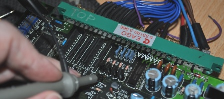
You’ll be looking at more insides than you expected. Against the side is a DVD control board, the top board at the back is for all the IO and the power supply sits underneath. As an aside the chip near the dip switches is where I believe the firmware lives which dictates whether you need DVD-ROM book type, every drive I have which doesn’t need this, has clearly had this chip removed and reinstalled along with a small resistor mod – it’s possibly an unauthorised hack.

The drive belt is easily accessed, gently push the tray in until it’s exposed. From there just replace the belt, it will actually untwist itself if not fitted correctly by pulling the tray out a little.

Stick one rubber block under the middle front edge of the PSU board.

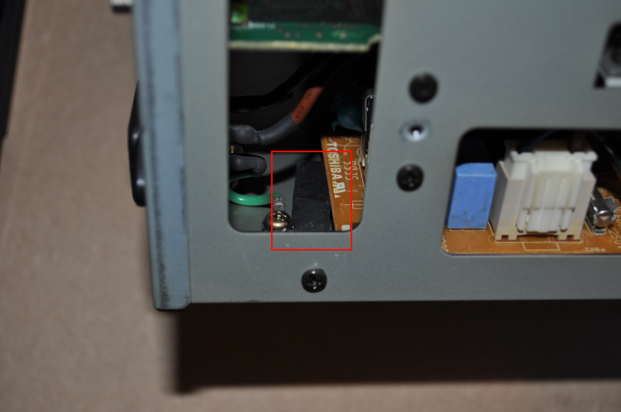
The second one is harder, first remove the plastic push-rivet and loosen the screw over the small metal panel on the back – it covers some unused IO ports.

Put the rubber block for the back of the PSU board in place using holes in the metal sides, and then slide it down about half way to the unpopulated area of the PCB with a screwdriver.

Once lined up in the right place, you can use the exposed IO holes to push the block under the PCB. You may need to use a finger to lift it a bit due to sagging.

Those are the two items you should address on any of these drives. If it’s working otherwise you can just put it all back together. It’s probably not though because you’ve found this article.
We’ll look at the laser next. Issues with this will cause genuine DVDs to play unreliably and skip, or DVD+R (or -R on new firmware) to not read and make rapid scanning sounds that sound like slippage when a disc tries to load. You can try the following steps to address this, make sure you have an original pressed DVD to hand for testing, and a burned DVD+R with DVD-ROM book type (you can get by with a DVD-R too but it may not actually play due to firmware). Plug the player back in, turned off, connect it to a TV with the S-Video output. Now remove the DVD top clasp. Obligatory note – NEVER look into a DVD laser, it can cause serious damage to your eyes.

With this removed you’ll be able to access the laser potentiometer, it’s at the back of the laser head unit and easy to reach with the cover removed. Turn it clockwise no more than 1mm at a time if you can’t read anything, or 1/2mm at a time if DVDs work but DVD+R make ‘skating’ sounds and fail. After each adjustment test media to see if it’s detected, if you have old firmware but only a DVD-R to test with, note that it will at least fail quietly as if the disc was checked, and display ‘check disc’ on the screen. Adjust the potentiometer with the drive powered off, when testing it’s sufficient to hold the top clasp in place rather than screwing it back on each time.

For reference it seems “a little under or over half way” is generally the sweet spot but you may have to go further with a tired laser. If you’re approaching one someone has messed around with, set it to 2mm under half way and try from there. If this procedure fails then something else is wrong – potentially the DVD control board, a cracked ribbon or perhaps the laser has simply failed beyond useability. Replacement laser / mechanism units are incredibly hard to find now, I think I bought the last NOS ones that exist. That said, I’ve repaired 5 of these drives so far and none of them had a bad laser.
The next problem is much more common (2 so far) and also harder to fix, the stepper motor that controls laser positioning can go bad. This causes a variety of issues – you may notice the tray ‘sometimes’ stutters when opening and closing, you may hear a very quiet high pitched beeping, you may see interference on the screen at rest while this is happening. It may sound like the disc is loading for a moment and then it may freak out and start clicking loudly. Alternatively things may appear to work until you get past a certain point during playback (generally a consistent position) and the disc will come to a stop, then start spinning up and down with the clicking sounds from the laser head. As above, if you can actually find one a NOS replacement laser / mechanism will solve this, but so will a $3 motor. You need a RF-300CA-11400 which are no longer produced but still cheaply and widely available – grab spares while you can. I found a RF-300CA-11400W also worked, the shaft is slightly longer which makes reassembly (and later disassembly) much harder and slightly risky, but it did the job.
With the top clasp already removed, take the two screws out of the tray – these stop it from ejecting itself. Once removed you can pull the tray slowly out of the front of the machine.

Remove the 4 screws holding the laser mechanism in.

Carefully remove the laser head ribbon, hold the laser in place while pulling this (it’s a simple push-fit) using the rail runners.

The next ribbon is a pain, it has a locking bar. Lift the back of the mechanism very slightly to reveal this and release it – pull the sides of the lighter plastic bar out in the direction of the ribbon, the ribbon should freely come out afterwards. If this is a struggle it is possible to pull the ribbon out without releasing it first. I don’t recommend it, but I did it once myself and it was fine.

Once the ribbons are disconnected you’ll be able to lift the whole mechanism out. From here I’ll use pictures of a new unit as I didn’t want to take the newly repaired one apart again… To remove the motor you need to desolder the wires, remove the drive gear and then undo the motor screws. However, there is significant risk of damage if you don’t remove other parts first. The drive gear has a black ring at the bottom, this is actually a VERY fragile part with magnets in it. There’s no way to remove this first, and if you try without removing the rest of the gear train, it will likely be snapped by the teeth on the second gear. Trust me I managed to do this to one, it’s irrepairable if that happens. Remove the circlip on one gear and the screw on the next gear to remove them.

Now you can remove the drive gear by pulling evenly upwards. Be very careful doing this, it will require moderate force to remove and it will snap if you aren’t careful. Pull around the three thicker parts of the plastic to avoid flexing the magnet ring. Sorry there’s no photo of this part, but desolder the motor wires then undo the screws.
Screw in the new motor then solder the wires on. Be careful refitting the drive gear, it may take some pressure especially with a W motor with the longer shaft. There are two sensors just under the magnet ring on the PCB, the distance between them and the ring should be 1/2mm.

Reassemble and cross your fingers! Note on refitting the third gear – it’s actually a dual gear with a spring designed to remove play in the gear train, you have to line the two halves up when refitting as they are out by a fraction of a tooth.
Finally if you do manage to find a NOS laser / mechanism unit and decide to go with that – remove the handling short for the laser diode. These stop static damage during handling and fitting, this is detailed in the manual that comes with them – English and Japanese versions are below for reference.


