Recently I’ve become aware of a growing number of Cave boards offered for sale (just search Yahoo auctions for many examples) which have colour faults. Usually these aren’t even advertised as being faulty, I’m not sure how much of that is honesty and how much is ignorance, but whatever the reason these are out there and they’re becoming easier to stumble upon.
One of the shmups forum members recently sold a Mushihimesama Futari to another, when it arrived he reported it as having bad colours. It ended up getting returned and then re-offered for sale as faulty. I asked if he wouldn’t mind sending it along to me for a diagnosis and possible repair since this seems to be a common fault on these very popular and valuable PCBs, and the owner agreed. I had a good hunch that it might be a similar problem to the Seta SSV colour drive issue as the symptoms were nearly identical.
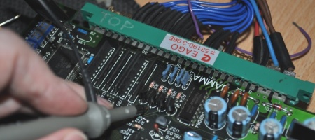
It arrived earlier this week, the parts arrived today, so I fixed it when I got home from work. This is what a Cave CV1000 board looks like:
This is what Futari shouldn’t look like – I’ll mention here the brightness and contrast were up a little too high from working on Sauro last night, it was a little sharper than shown here, but still washed out and lifeless with a blue/green tint. I think what catches people out here is the colours are all still there to some extent.
Go and see how many on Yahoo are tinted… Yeah. I suspect this happens to any CV1000 board which sees a lot of field use, from around the manufacturing date of Futari – possibly all CV1000s in fact. Futari was a very popular title and many were sold/operated, which is probably why it always seems to be this game. Next photo shows the colour output section.
See U14, U15 and U16? Those are the colour drive amps for red, green and blue respectively. Pin 1 on the bottom left is the output, pin 3 on the bottom right is the input. These are AD8061ARTZ-* devices, the rest of the part code is simply the packaging it’s supplied in. Click here for the datasheet.
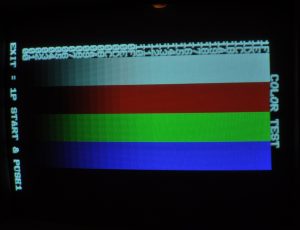
The components which generate the video signal can’t actually drive the load of a CRT monitor, so these sit in-line and do that job. This is where the problem was most likely to be. To check something like this, you need a nice static image of some kind, so I put the board into test mode.
What’s interesting here is that while we know theres a tint to it in game, the colours look sort of even here, this is also similar to how the problem looked on SSV games. You need an oscilloscope to do this properly, we simply take a look at the colour output on the JAMMA edge, pins 12 and 13 in this case for red and blue.
First up was blue, looks nice and healthy, but the next image shows red – clearly a much weaker signal.
So we know that red is definitely bad, but that doesn’t mean to say it’s definitely the AD8061, the input to that could be bad – so we check the signal on pin 3 for the blue and red chips respectively:
And as we hoped to find, the inputs look fine for both channels.
Note that I did check green input and output too, but it’s not shown here. If you get a board which looks really bad I’d check all three – the output should at least be as strong as the input. At this point we know U14 is bad, so it’s time to bust out the SMD tweezers to remove it since these chips are really too small to safely remove any other way.
Do not take photos like the above unless you’re just doing it for illustration and the iron is cold… It won’t do the PCB any good. Anyway, the component should come up easily enough and leave you with this.
Switch to a normal pointed tip iron and melt the solder on the 5 pads as it will make the next step easier. Apply flux to the pads if you’re using hideous unleaded solder, this isn’t usually required if you use solder with lead and a flux additive. Use a pair of normal chip tweezers to hold the new part in place, and reflow one of the pins. Then check the angle is correct, put some pressure on the part and reflow the others in quick succession a couple of times. You can use a hot air pen for this but honestly for jobs like this I find a fine point iron and doing each pin by hand gets a stronger result. When all 5 are reflowed, go around them again and add a tiny dab of solder to the iron while you do so. Clean the flux off with some flux remover on a cotton swab, it will look nicer.
That was as good as I could get it, looks better in person but catches the flash badly. As I say you will need a fine tip iron for this as the legs are only about 0.5mm wide. Time for test mode again and checking the red output on the oscilloscope.
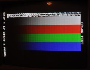
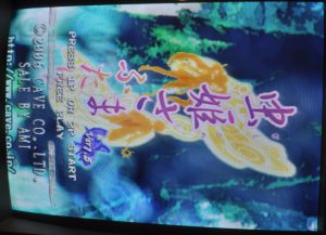
Much, much better. How does the game look now?
It looks perfect. There you go, the CV1000 colour mystery is solved.


