There are some collectors out there who want things perfect, the way they came from the factory.
Well…. Let’s just say that’s not always a realistic fantasy. I’ve had an odd looking (possibly Korean) Lady Killer PCB for a while, it’s a tile flipping game (with women who strip of course). Actually quite a fun little game, you could easily replace the backgrounds with anything and it would be a respectable game.
I saw another board on ebay, much smaller but still with the same essential layout and PCB labelling and since it was cheap picked it up. When it arrived I noticed two things – firstly it was licensed to Electronic Devices (in Italy) and the code / sample ROMs were different so I’ll be sending them to the MAME people. Secondly the sound was incomplete, all the synth sounds were missing leaving just samples (and the music just drumbeats). I didn’t complain to the seller after giving it just a quick look over, because it became very quickly obvious the game left the factory this way. Comparing it to the Korean LK board and a Mitchell Karate Tournament which uses the exact same PCB, it was obviously wrong.
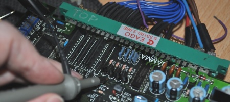
Looks fairly normal, but the sound coming from the YM2413 just vanished, never reaching the left op-amp which I knew it needed to from checking the similar boards. Let’s take a closer look.
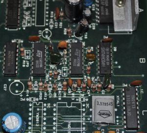
There are a couple of things wrong here. The PCB is poorly labelled in places, that resistor at R14? Well R14 is actually the position to the right of it, it’s sat in a space for a filter cap. C10 and the other filter to the left of it are also missing, as is the filter for the LM324 op-amp on the right. A couple of these aren’t just filters, they’re the actual signal path… You need to do the following:
1) Move the resistor at R14 one space to the right
2) Install 0.1uF (104) filter caps at PC where the resistor was, C10 and the one to the left (which I can’t read due to a through hole).
3) Install a 0.1uF (104) filter cap above the LM324 on the right.
When you’ve finished it should look a bit like this:
Finished? Nope – not content with putting components in the wrong places or not at all, the board also has a track layout error…
4) You need to add a wire link between pins 8 and 9 of the LM324 in position 5B, like this:
And now you’ll have full sound! I thought I’d document this one because with the track error there’s no way there’s just one of these out there, if you ever come across one this is how to make it work.


