One of my cabs is a Missile Storm I’ve had a love/hate relationship with for some time. It came from the famous Duke Of Lancaster cab raid, I actually had two of them – put all the best parts into one and restored it, sold the other as a project. Since then I’d been trying to sell it due to space limitations in the house – and finally I found a buyer who wasn’t going to be a total loss.
Switched it on to test before sending payment details and … well obviously the flyback started sparking to the chassis. Not only that, but the game board kept resetting which was an unrelated and even more annoying story I’ll cover another time. In the garage the original chassis from the second machine was lurking in a box – the second machine arrived with a necked monitor and I’d put an old WG in there just to get it going. With the second old chassis fitted, the screen worked but was unstable during warmup and the image just wasn’t as vibrant as the sparky one, even after much adjustment.
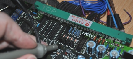
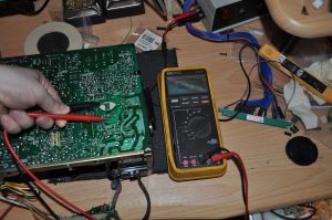
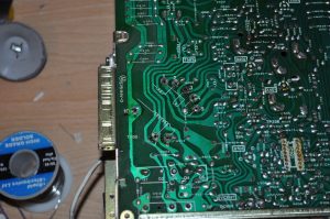
I spoke to Grant on Arcade Otaku about this, and he said it was a fairly common fault but he didn’t have any spare flybacks he could sell me, so I ordered one from Twisted Quarter, which arrived a few days ago. Off to the repair bench.. As you can see, it wasn’t too messy for something made in 1980 and left on a ship for 25 years.
Obviously we’ve skipped the removal step of discharging the tube to get here, but that large grey capacitor can still hold quite a charge . You can short this out if need be, as you can see mine had been unplugged for a few weeks and there was nothing left to worry about.
First step to removing the flyback is to desolder the white wire which goes to one side of the focus control. Of course this is the one photo I got the focus on the camera wrong with…. Make sure you keep the rubber boot to one side afterwards.
Remove the screws holding the flyback to the chassis frame.
And finally desolder the flyback, this part was made much easier by having a proper vacuum desoldering iron – it’s pins 1-6 and 10. I added new solder first before trying to remove the old as it helps to melt it down properly.
Thanks China! At least someone still makes the parts. Note the white wire won’t come threaded through the chassis mount so remember to do that before you fit the part.
Now put it all back together remembering the rubber boot you set aside. A note of advice here, I found I had to spend quite a lot of time slightly bending the pins to get a fit. Once I did, with the part flush against the PCB, tightening up the frame mount screws caused the large ferrite to rub on the frame (which is where the old one was sparking actually), and caused the whole PCB to flex. Looks like these parts aren’t quite built as precisely as they could be. As a result I ended up desoldering it again, bolting the flyback to the frame first (with spacer washers), and then soldering it. It leans slightly and the pins don’t stick through very far in places, but it fits better overall. Also I took this photo before realising I’d forgotten to trim the length of the white wire, keep is short enough to have slight slack but no more.
Time to discharge the monitor for a chassis swap – I use a HV probe but you could just as easily use a screwdriver and a bit of wire. Note ground clip top left, and note do this with one arm nowhere near the other or the cab.
Remove all the wires to the chassis, and then the chassis itself. You need to do the yoke cable near the flyback, a ground wire that goes to the neck board, the video input which is near the tube on the left, the power, the degauss wires which are on the bottom left, and finally the neck board. Be very gentle removing that, as the neck and connector are easily broken. A screw each side holds the chassis in place.
Fit the repaired chassis, hook up everything except the video input. Sanity check everything and … switch it on. If all is well there will be no smoke, no blue flash, the house fuse won’t trip and it will just crackle briefly and sit there quietly humming. Check the B+ setting is 120v (R909 on the chassis, measure from the furthest lug of the large resistor on the left – for a full guide including photos check out the excellent writeup on Bob Roberts site).
I left it like that for about 15 minutes, then turned it off, plugged in the game PCB and the video feed. After a few moments tweaking the screen and focus controls I had a nice stable image.


