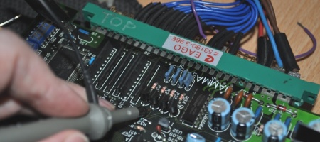
I’ve had a Japanese Battle Garegga for a while, but one thing which had always bothered me is that it was fussy about which cabs it would work on and which it wouldn’t. I found that quickly toggling the power would make it boot every time, but recently picked up one sold as faulty because even with this trick the owner was unable to make it work. I’ve also seen this problem referenced on the Arcade Otaku forums (in one instance affecting the sound CPU) and people were stumped, blaming power supplies.
You can fix this, and you’ll wonder how this ever happened in the first place:
That’s how they look when it happens, it varies a bit but it’s a common theme of square blocks of corruption or the game may boot with sound errors. It looks pretty dramatic, in fact I thought my PCB was broken the day I received mine having not seen the fault before. I checked the 5v and it was perfect, and eventually I checked on another cab and the game came to life with no drama at all. Here’s the problem:
Now before I show you how to fix this, lets explain why the above part is a problem. The small 8 pin chip MB3771 is a voltage monitor, it’s the job of the voltage monitor to release the RESET line when the power supply has come up to operating voltage. Here’s the Fujitsu datasheet for the part in case you’re curious.
There are three important pieces of information in there, one is the voltage at which the 3771 will reset the game, 4.2v. The second is the function explanation variable Tpo, and the third important part is their example reset circuit:
 See that Ct? That’s the small capacitor I highlighted in red. In every game I’ve seen with a 3771 based reset, it’s generally a capacitor in the 10uf range. What this does is cause a small hold delay between when the 3771 sees 4.2v and when it actually releases the reset line, which allows the power supply to come up to voltage properly before the game tries to boot. This matters because without a delay the 3771 is happy to trigger a reset and boot at 4.2v, less than the 5v required for reliable operation of half the logic chips on the PCB.
Unfortunately, Raizing chose to stick a standard 0.1uf decoupling capacitor in there just like all the others on the board. That is 100th of the required value, providing zero delay at all and causing the game to try to boot at 4.2v. Now if you have a power supply that comes up to speed very quickly, you don’t have a problem. If the power comes up a little more slowly you do have a problem, and you end up with a crashed CPU. The reason switch flicking sometimes works is that the PSU caps haven’t completely drained and it appears to fire up more quickly.
So basically, its either a design flaw or a factory assembly mistake – but the end result is the same and all you need to do to fix it, is put a proper cap in there – I used tantalum 10uf/16v beads. Sorry for the picture focus, but here’s the Japanese Garegga with the new cap fitted:
Note that all the small caps actually look like resistors on this type. Personally I hate them. Make sure you fit the tantalum the right way around – the positive pin goes to pin 1 on the MB3771, the negative goes to ground. Other variants of the board use more traditional 104 caps, here’s the fixed Chinese board:
As an aside, the games made after Garegga use proper capacitors in the reset circuit, it only appears to affect this one game, and potentially Sorcer Striker too. Additionally it’s very likely that there’s some variance even within identical boards, sometimes you get lucky or unlucky with components being more or less sensitive to running under voltage. With the cap correction the boot problems will be gone, and this is what you’ll always end up with (unless something else breaks):


